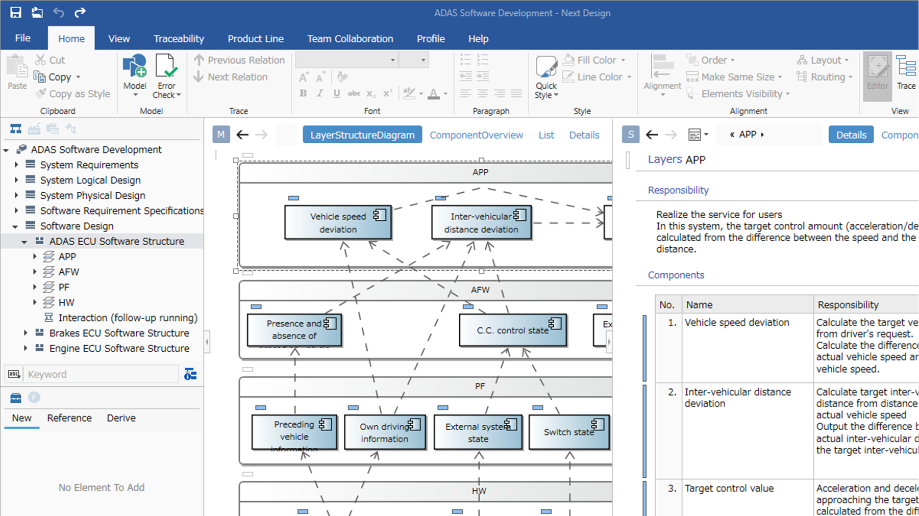
Next Design allows you to create a variety of looks for your design information. From Word-like documents, to Excel-like grids, to diagrams with a bird's eye view, there is a huge variety of ways to present your design information. Standard UML/SysML views are of course also possible.

-
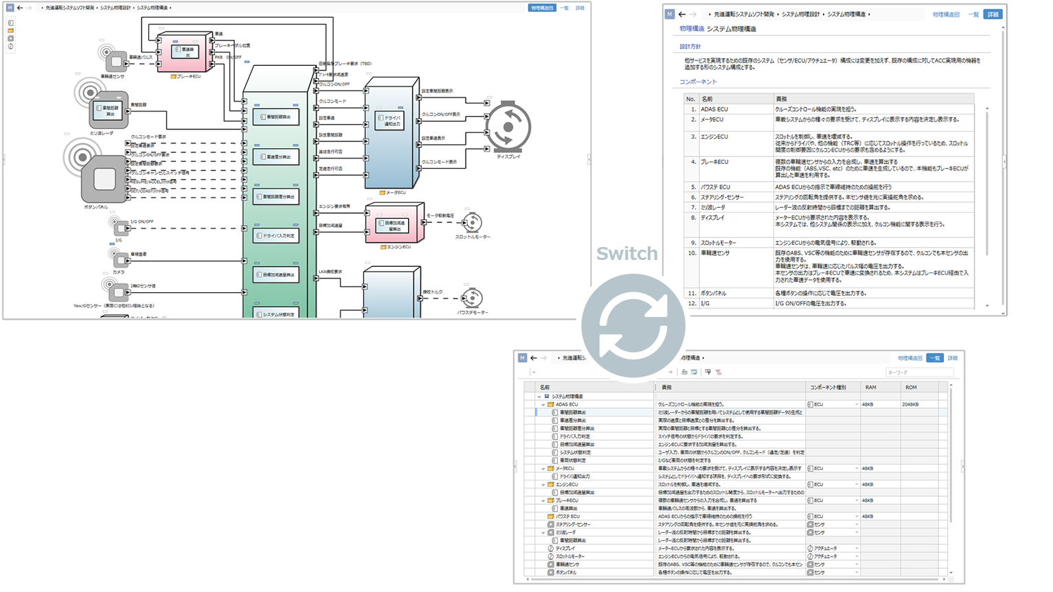
Switch between multiple views to suit your needs
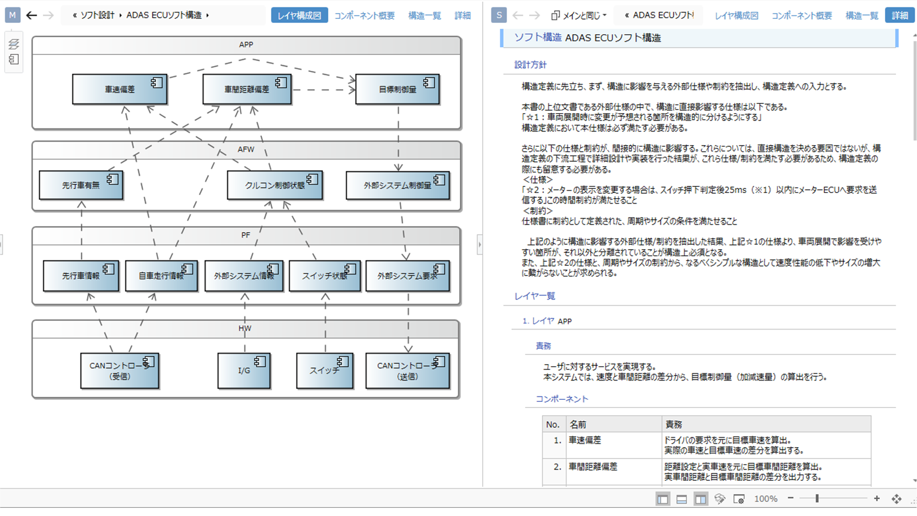
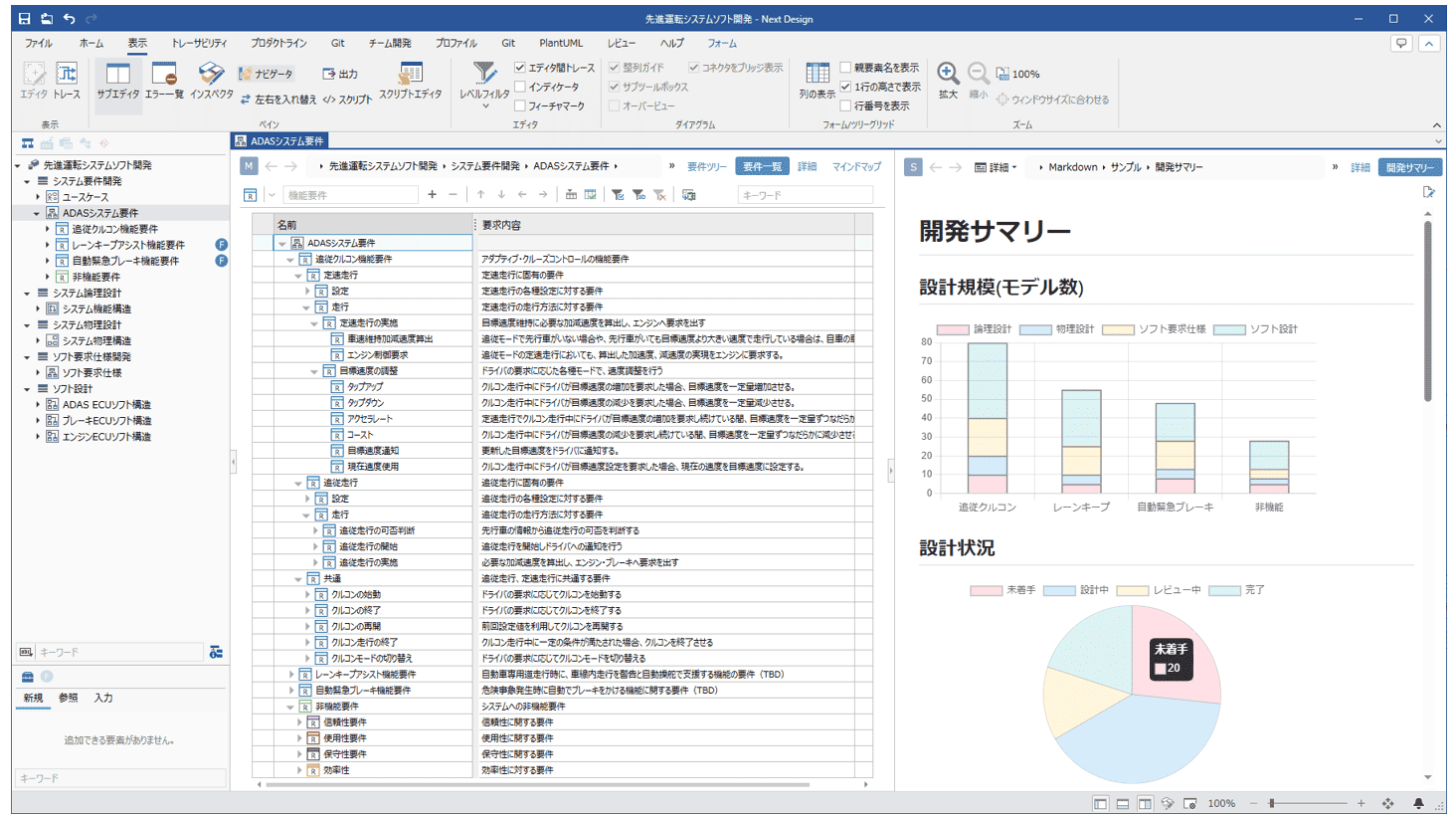
Multiple views can be set up for a single piece of design information You can set up multiple views of a single piece of design information, allowing you to switch between them according to your needs and objectives. For example, you can switch between a diagram for a bird's eye view and a document for details. You can even switch to a dedicated look for review purposes.
-
Integration of models and documentation
The model provides a graphical overview of the design and a Word-like and Word-like documentation for seamless design. This allows you to design seamlessly.
-
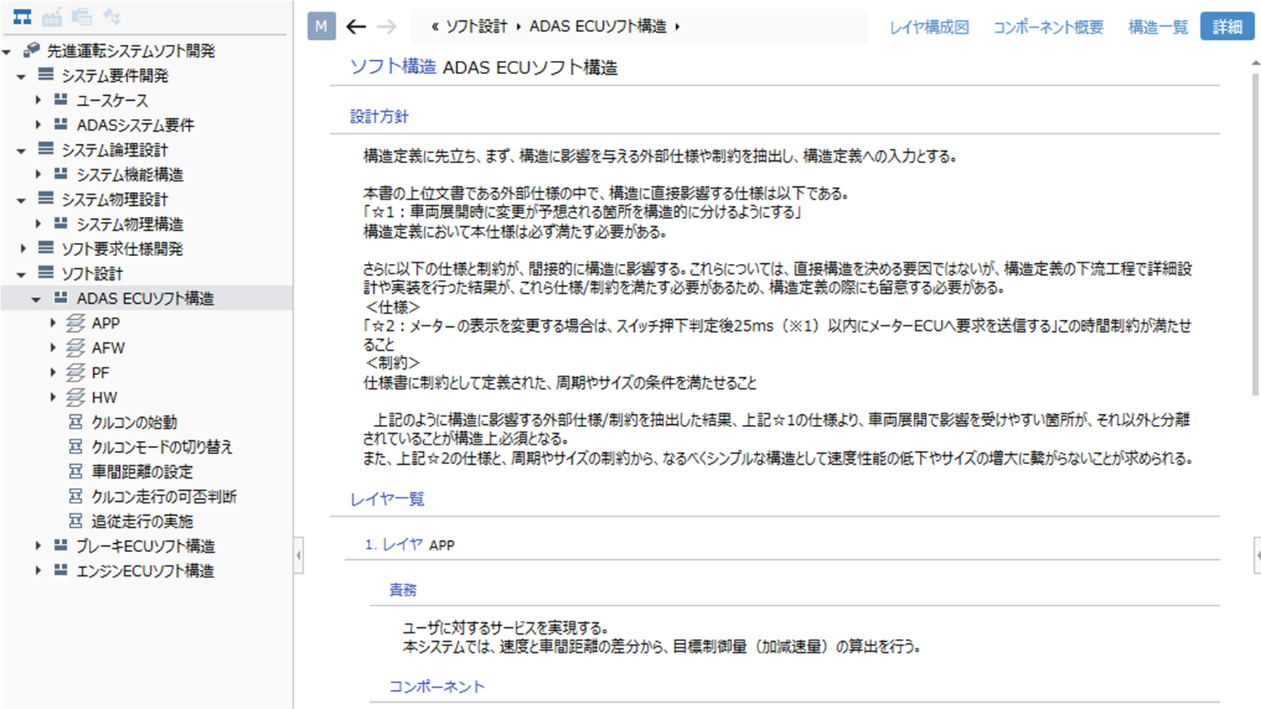
Document
View and edit metamodel design data in a Word-like document format. Hierarchical representation of text and tables allows the model to be displayed in a document-like style.
-
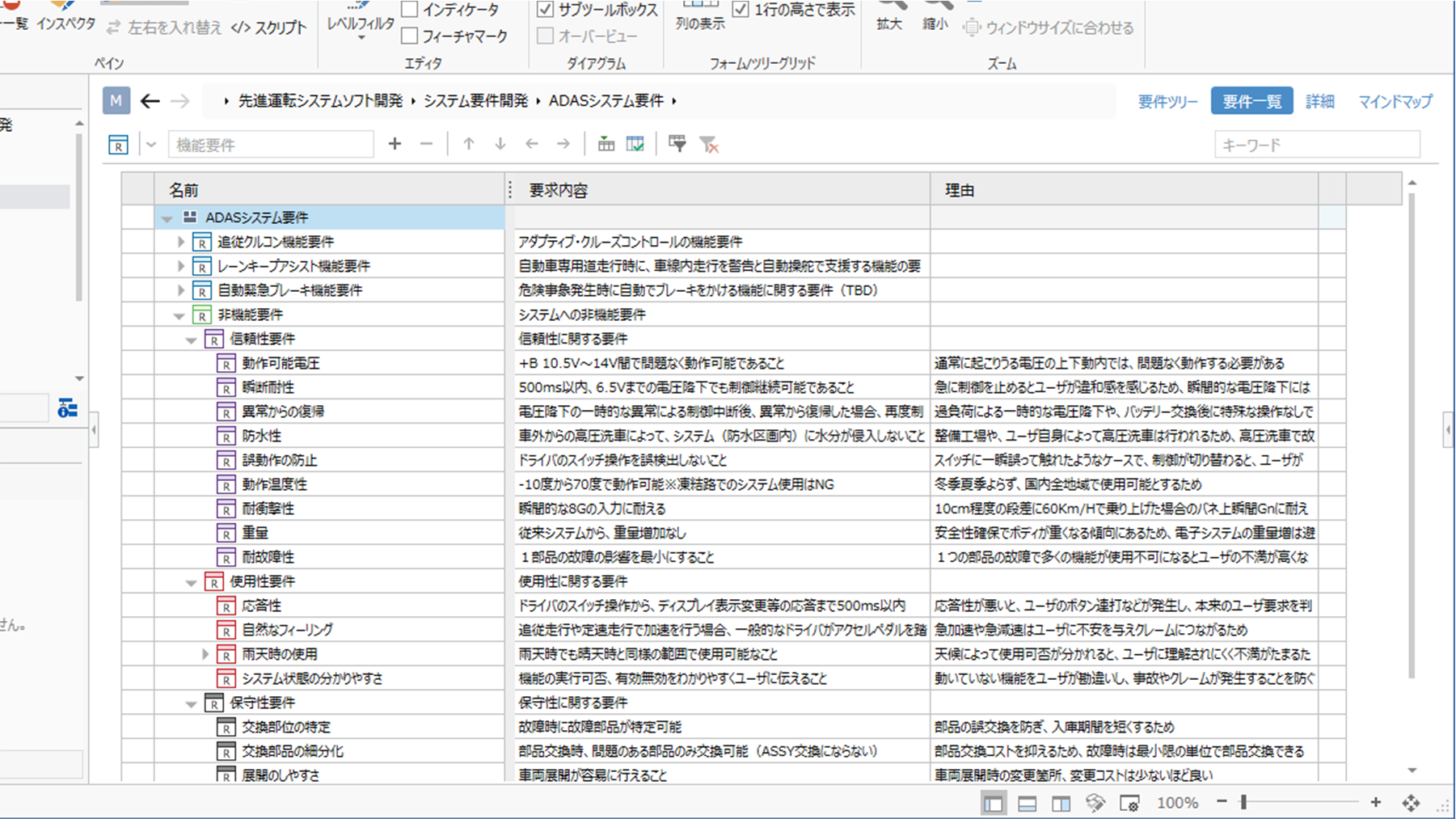
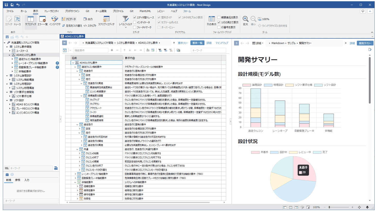
Tree Grid
The Excel-like appearance allows users to view design information hierarchically in a list.
Models can be edited as if you were editing a table, with auto-fill for batch input and cell-by-cell copy and paste.
Color can be set for models, and models can be highlighted or color-coded.
Cells can be labeled with notes and line numbers to facilitate communication during reviews. -
ER Diagram
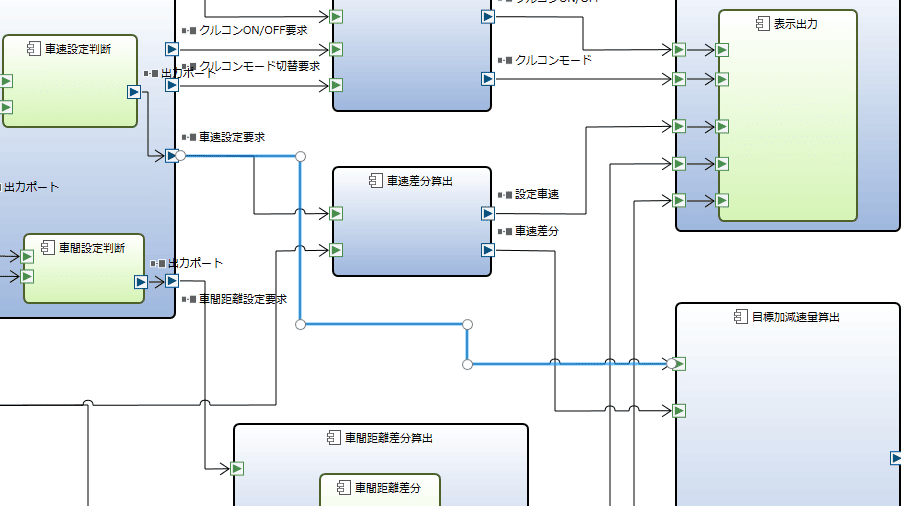
The use of graphical representation provides a bird's-eye view of the relationship between design information.
Highlighting selected related lines and skipping over intersections allows you to see at a glance where they are connected, even if the path of the related lines is complex. -
Tree Diagram
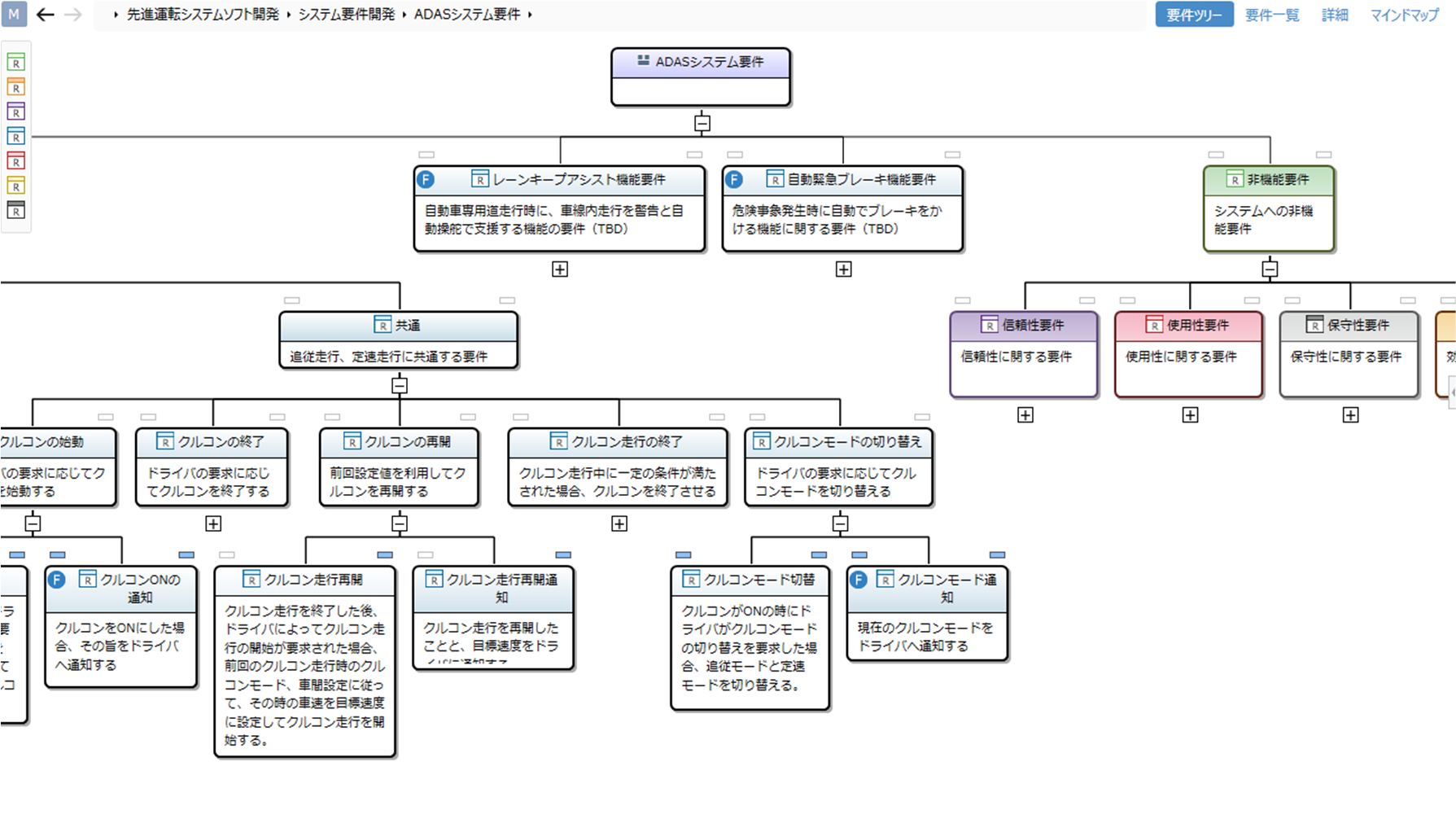
The tree representation gives you a bird's eye view of the hierarchical relationship between the design information.
-
Sequence Diagram
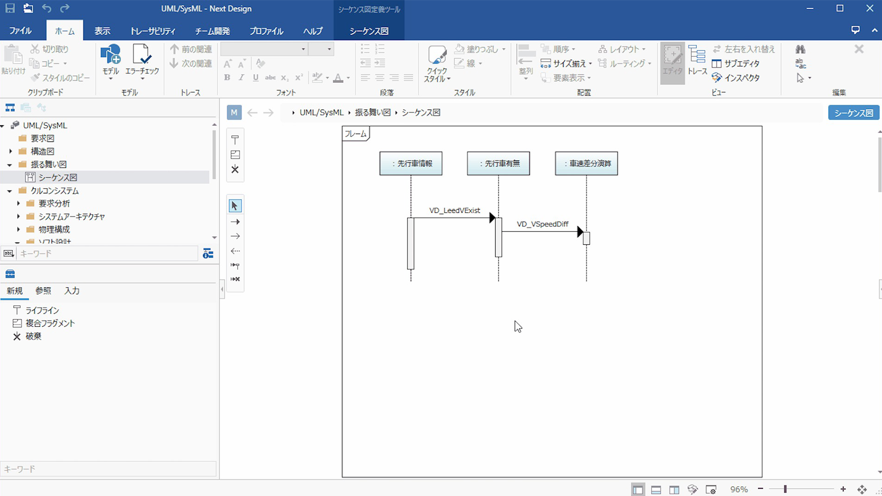
The sequence diagrams used to represent the behaviour have been developed in-house and are very intuitive. Even if you add lanes in between or reorder them If you want to add lanes between lanes or reorder them, the lifelines and messages move in tandem, so you don't have to.
Lifelines and messages can be associated with models, so that structure and behaviour can be designed consistently.
-
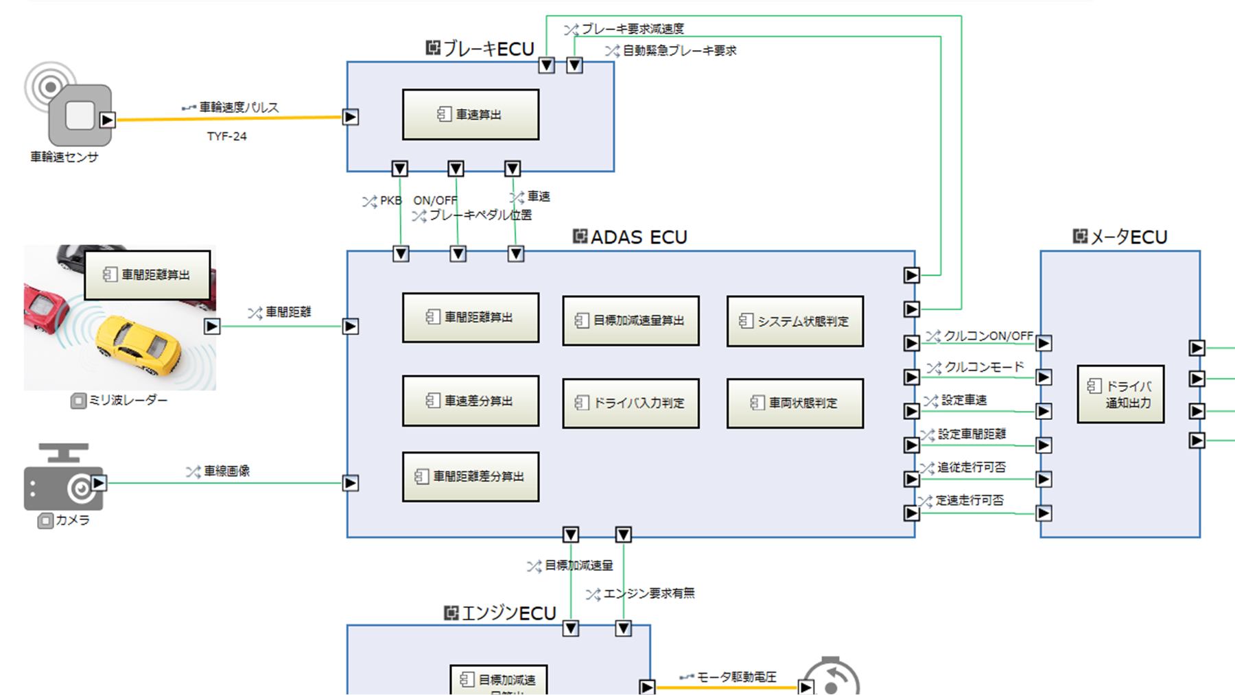
UML/SysML
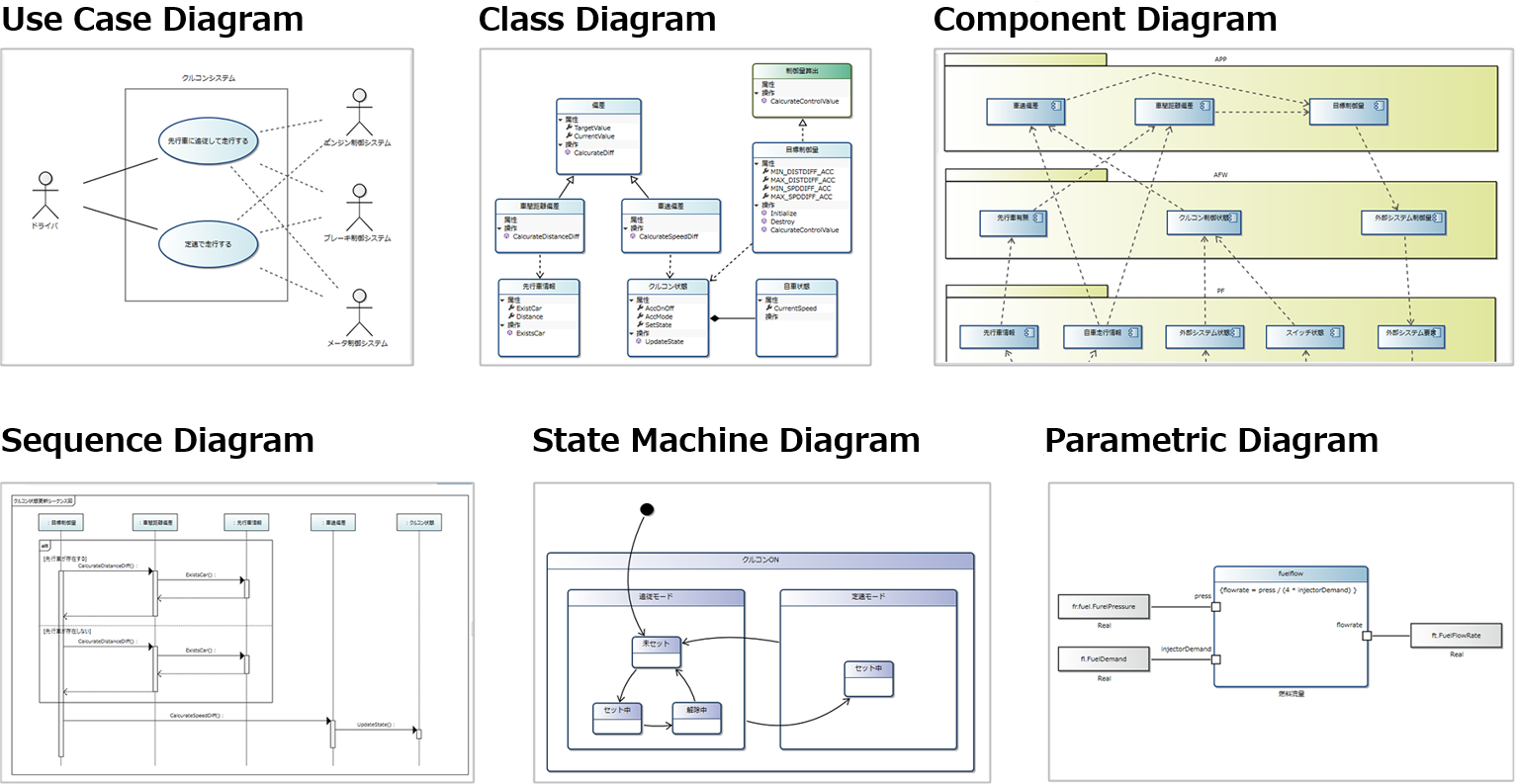
Requirements diagrams (requirements diagrams, use case diagrams, use case definitions), structural diagrams (class diagrams, component diagrams, use case definitions), and other diagrams that conform to standards such as UML/SysML. use case definitions), structure diagrams (class diagrams, component diagrams, package diagrams, deployment diagrams) UML/SysML), structural diagrams (class diagrams, component diagrams, package diagrams, deployment diagrams) and behavioural diagrams (sequence diagrams, state machine diagrams). state machine diagrams). The diagrams can be further customized.
-
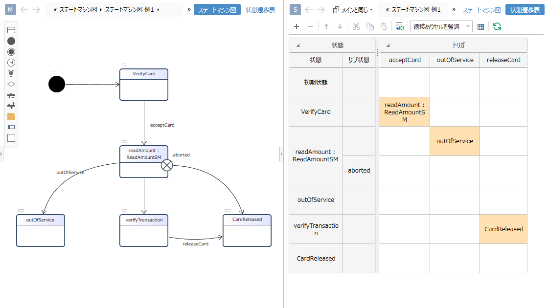
State Change Table
Supports state transition tables, an expression frequently used in embedded software development.
State machine diagrams and state transition tables are linked, changes are updated in real time, and they can be switched between each other for editing.
In addition, cells can be highlighted and set to Ignore or NotHappen to ensure that there are no omissions in the design. -
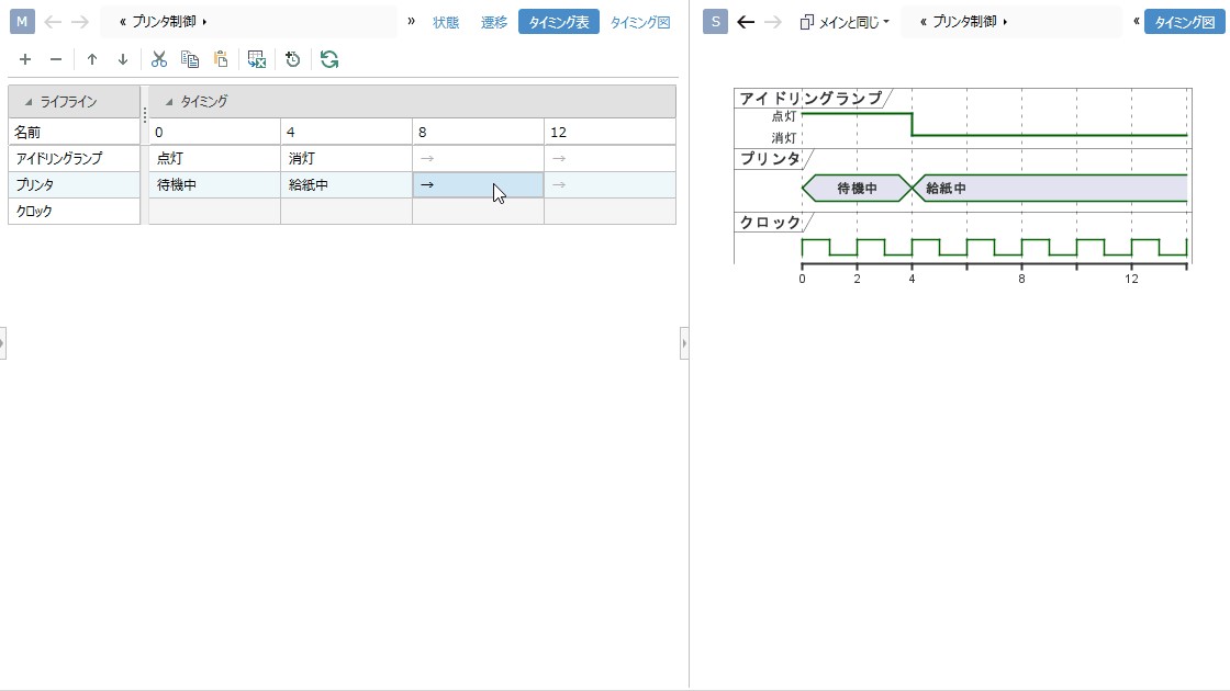
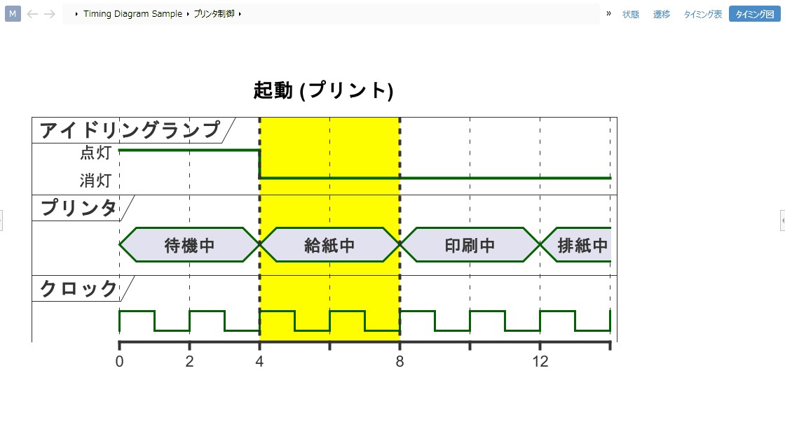
Timing Chart
Supports timing charts that can express the relationship and behavior of signals on a time axis.
Timing charts can be easily created from the design information on digital transformation.
The traceability to requirements and constraints makes it easy to see if there are any design omissions.
Furthermore, since all design information is available at digital transformation, it is easy to achieve efficiency through independent verification and automation. -
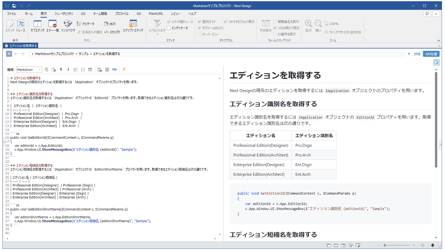
markdown notation
The expressive power of markdown notation makes design information easy to understand. It also supports PlantUML, Mermaid, Graphviz, and ChartJS, which are markdown extension notations, allowing you to embed a variety of graphical representations. Web pages can be displayed by specifying URLs, and content can be generated dynamically by embedding scripts.
-
A greater variety of graphical representations
Diagrams such as flowcharts, mind maps, GSN diagrams and Process Flow Diagrams (PFD) can also be easily custom defined. Major diagrams can be represented in Next Design.
-
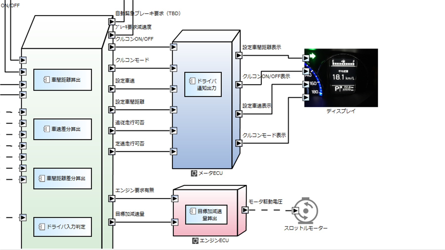
Custom diagrams with own shapes and images
Instead of built-in shapes, you can create custom diagrams using your own icons and images.
-
English interface
Next Design is also available in English as a standard feature, making it easy to collaborate with or commission overseas.


