


Part 2: Experience Customization Tailored to Your Environment
In this part, you will check Next Design's customizability and extensibility to support various workflows, and experience the concept of "a design tool that fits your field."
While this sample focuses on embedded software development, you can apply it to workflows other than embedded software development by customizing a general V-model-based sample to fit your own development.
Steps
Let's experience Next Design's customizability and extensibility in this order.
1. Let's check the profile and target phase
Check the overall picture of the target phase
Open in a new window
Open in a new window
Task Details
In Next Design, the types and structures of information handled in design are defined as "profiles." The embedded software development base package comes with pre-configured profiles aligned with the V-model of typical embedded software development.
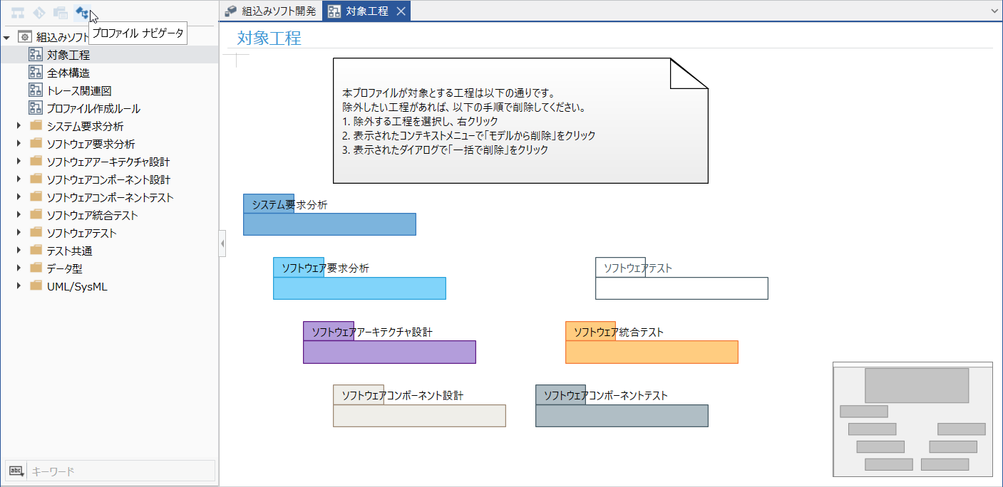
Here, open [[Class Diagram] Target Process] from the profile navigator to see an overview of the processes defined in the package.
Procedure
- Open the sample project [Embedded Software Development] in Next Design.
- Switch the navigator to the profile navigator.
- Double-click the following class diagram in the profile navigator to open it.
[Class Diagram] Target Process
- Verify that the class diagram defines the requirements analysis/design phases and the test phase along the V-model.
The requirements analysis and design phases define the following processes:
- System Requirements Analysis
- Software Requirements Analysis
- Software Architecture Design
- Software Component Design
The test phase defines the following processes:
- Software Component Test
- Software Integration Test
- Software Test
- Return to the model navigator and verify that when adding a model at the project root, the processes checked in the class diagram are displayed as selectable options.
Goal
The embedded software development base package includes profiles aligned with the standard V-model, allowing you to create software development models simply by adopting the package.
2. Let's narrow down the target processes
Limit to the processes you use
Task Details
In actual development, the scope of Next Design application varies by project. By customizing the embedded software development base package profile, you can restrict the choices when adding models to only those processes used in your project.
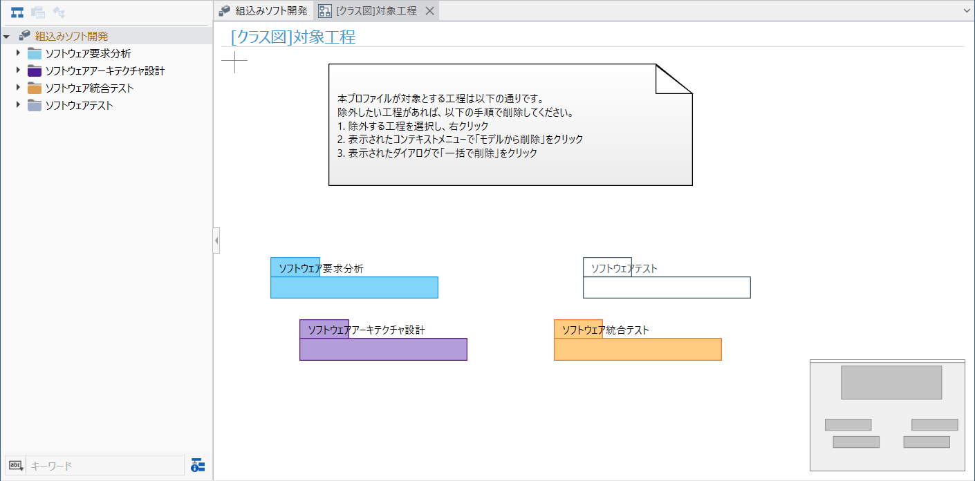
Here, assuming a minimal V-model that includes upstream processes, we will narrow down the applied processes to the following four:
- Software Requirements Analysis
- Software Architecture Design
- Software Integration Test
- Software Test
Procedure
- Switch to the profile navigator and open the following class diagram:
[Class Diagram] Target Process
- On the class diagram, select the processes to be excluded from the current application scope one by one, starting from the subsequent processes.
- System Requirements Analysis
- Software Component Design
- Software Component Test
- Right-click the selected process and select [Remove from model] from the context menu.
- When the dialog appears, click [Remove all].
- Repeat steps 2 to 4 to remove the 3 processes that are not included in the application scope.
- Verify that only the following 4 processes remain under [[Class Diagram] Target Processes].
- Software Requirements Analysis
- Software Architecture Design
- Software Integration Test
- Software Test
- Return to the Model Navigator and verify that the selection options when adding a model at the project root are limited to the 4 remaining processes.
Goal
You will understand that by starting with the standard package profile and keeping only the necessary processes to match your project's application scope, you can tailor it to fit your own development process.
This procedure is also documented in the manual for the embedded software development base package.
Reference: Package Manual > Customization Guide > C1: Restricting and Using Application Scope and Processes
3. Let's add the necessary design data
Enabling design rationales to be recorded
Open in a new window
Open in a new window
Task Details
Based on the design information defined in the standard package, you can add information required for your own development.
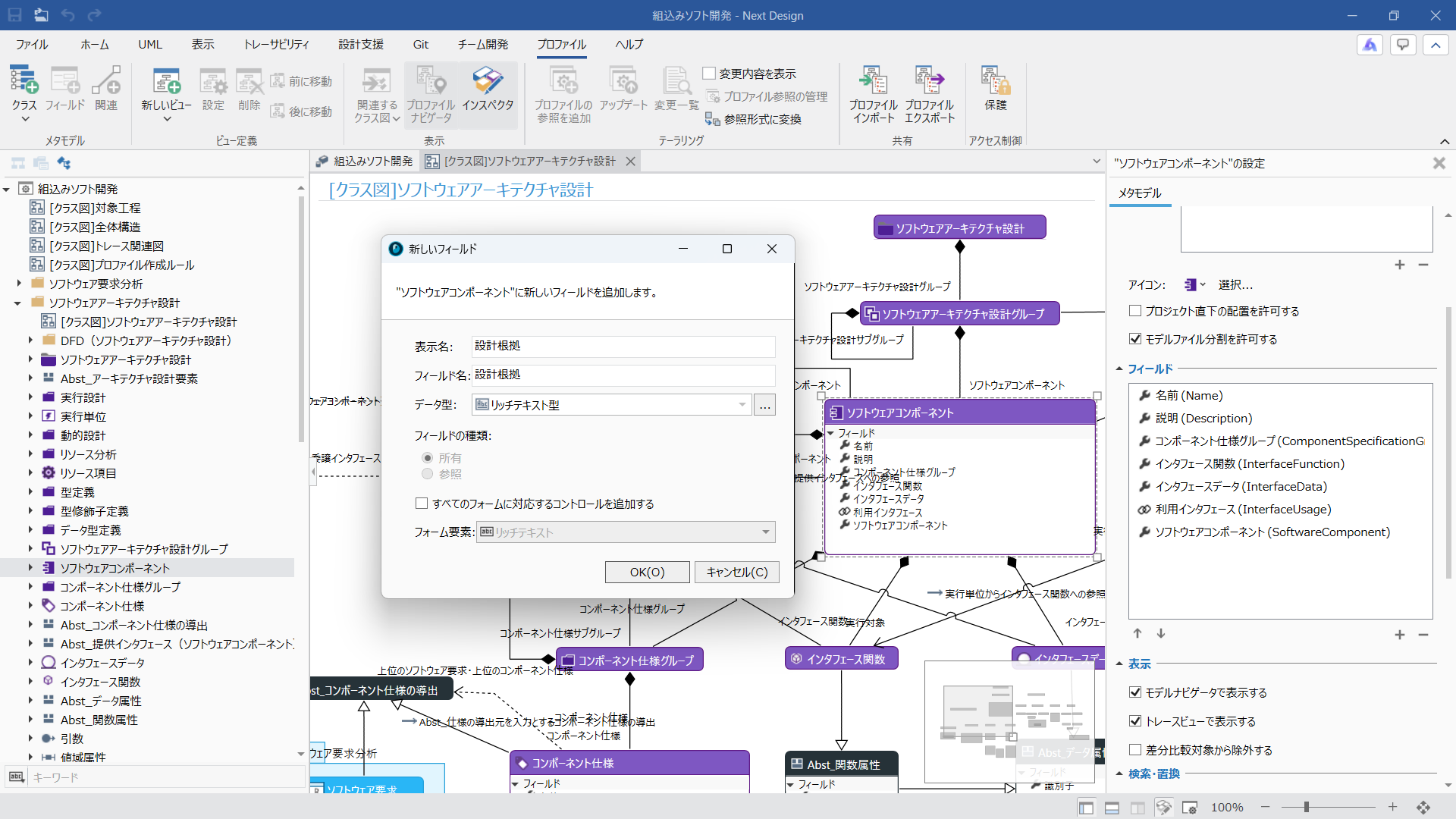
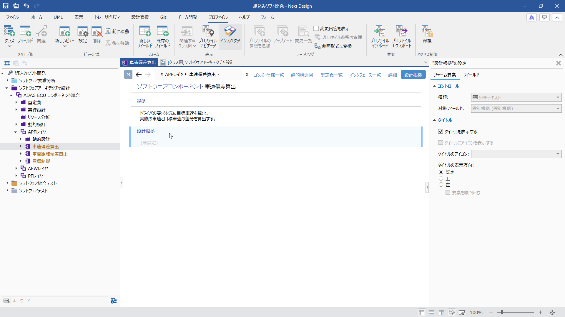
Here, as a representative example of adding design data, we will add a rich-text type [Design Rationale] field and its editing form view so that design rationales such as interface designs can be documented for each software component.
Procedure
- Switch to the Profile Navigator and select the following class from the tree.
Embedded Software Development > Software Architecture Design > Software Component
- Click [View] > [Pane] > [Inspector] on the ribbon to display the Inspector for configuring details on the right side of the screen.
- Open the following class diagram from [Profile] > [View] > [Associated Class Diagrams] on the ribbon.
[Class Diagram] Software Architecture Design
- [Software Component] Add the following fields to the class.
Verify that the [Software Component] class is selected on the class diagram, and click the [+] icon in the [Fields] list displayed in the Inspector on the right side of the screen to enter the information as follows.
Display Name: Design Rationale
Field Name: DesignRationale
Data Type: Rich Text
Add a control compatible with all forms: OffClicking the [OK] button adds the [Design Rationale] field to the [Software Component] class.
- Next, add a view to display and edit the added [Design Rationale] field.
First, return to the Model Navigator and open one of the target [Software Component] models. Here, open the following model:
Embedded Software Development / Software Architecture Design / ADAS ECU Component Integration / APP Layer / Vehicle Speed Difference Calculation
- Click [Profile] > [View Definition] > [New View] > [Document] on the ribbon, and enter the settings on the screen as follows:
Display Name: Design Rationale
View Name: Design RationaleClicking the [OK] button adds [Design Rationale] to the view selection options, allowing you to switch to it.
- Place the newly added [Design Rationale] field in the newly added [Design Rationale] view.
Right-click the view title area, select [Profile] > [Add Existing Field] from the context menu, and select the [Design Rationale] field from the [Field] selection options.
Clicking the [OK] button adds the [Design Rationale] field to the [Design Rationale] view.
- Since the [Design Rationale] view is added commonly to all [Software Component] models, you can record design rationale in any model.
Goal
By adding fields and views to existing classes, you can understand how to manage design information required for your development as part of the model.
This procedure is also documented in the manual for the embedded software development base package.
Viewing the Metamodel of All Design Data
Task Details
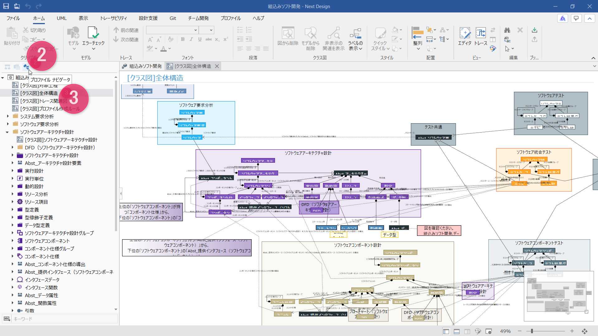
The overall structure of the design data handled in Next Design is called the "metamodel". You can check the structure of this metamodel in a class diagram format, or customize it to suit your own development.
Here, let's take a look at a part of the metamodel defined in the sample.
Procedure
- Reopen the sample project [Embedded Software Development] from the Next Design start screen.
- Switch the navigator to the profile navigator.
- Double-click the next class diagram in the profile navigator to open it and check the overall structure of the design data.
Class Diagram Description [Class Diagram] Overall Structure Class diagram showing the main structure and relationships of design data for each V-model phase [Class Diagram] Traceability Diagram Class diagram showing relationships for traceability information between phases Software Architecture Design > [Class Diagram] Software Architecture Design Class diagram showing the structure and relationships of design data handled in the software architecture design phase
Goal
You will understand that the structure of the design data handled in Next Design is defined as a metamodel, and that this structure can be verified in the class diagram included in the profile.
4. Experience the extensibility provided by extensions
Automatically extract the scope of impact
Task Details
The embedded software development base package includes extensions that automate routine tasks by leveraging models.
Here, you will execute [Extract IF Impacted Areas] to identify dependencies from interfaces and components on the static structure diagram, and experience how managing design information centrally as a model allows you to automatically extract the scope of impact when changes occur.
Procedure
- In the model navigator, select the [Software Architecture Design Group] or [Software Component] model.
For example, select the following model.
Embedded Software / Software Architecture Design / ADAS ECU Component Integration
- Switch the main editor view to [Static Structure Diagram].
- On the static structure diagram, select one interface or component whose impact scope you want to check.
- Click [Design Support] > [Impact Analysis] > [Extract IF Impacted Areas] on the ribbon.
- Verify that the extension identifies interface dependencies and allows you to check the scope of impact.
Goal
You will understand that by managing design information as models, extensions can automate the process of tracing relationships between models, enabling you to efficiently review the scope of impact when changes occur.
Take a look at the extension's source code
Task Details
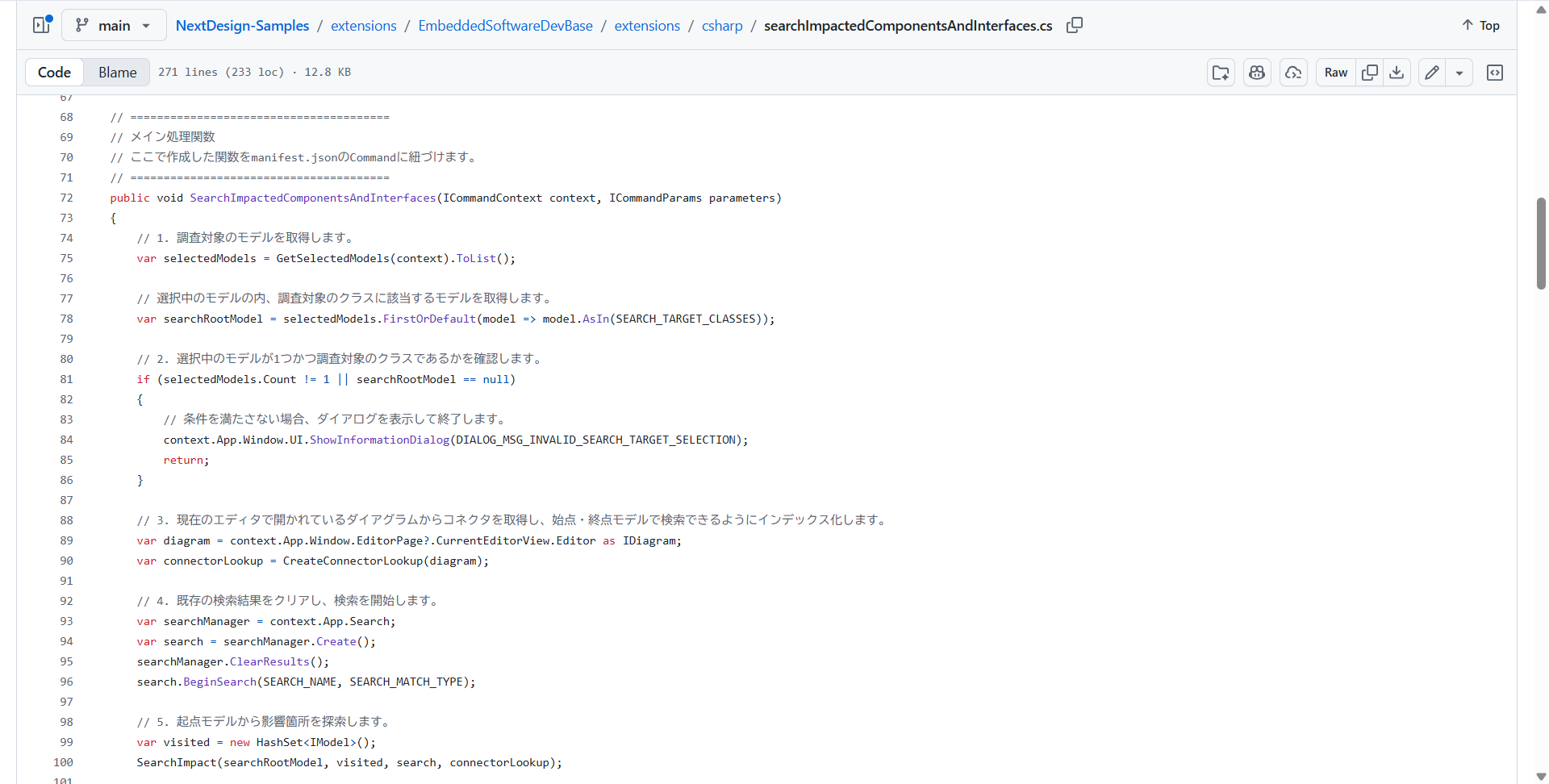
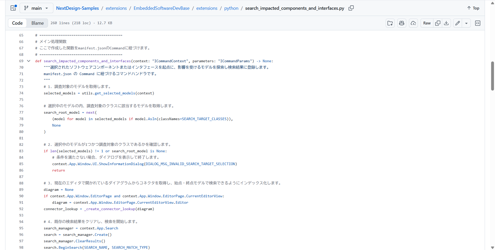
The source code for both C# and Python versions of the extensions included in the embedded software development base package is publicly available. You can reference the source code as implementation examples and build upon them to extend functionality for your own workflows.
Here, you will check the published source code and the automation features included in the package, understanding how Next Design can be extended through programming.
Procedure
- Check the extension source code for the embedded software development base package published on GitHub.com.
The source code corresponding to the extension feature [Extract IF Impacted Areas] executed earlier can be found at the following link.
C# version source code:
searchImpactedComponentsAndInterfaces.csPython version source code:
search_impacted_components_and_interfaces.py - In addition to automatic impact scope extraction, the embedded software base package includes extensions that automate routine tasks such as the following:
- Batch Creation of Software Requirement Models
- Batch creation of test result models
- Sequential re-numbering of IDs
- Automatic extraction of impact scope
- Automatic aggregation of test results
These source codes can also be checked from the following links.
https://github.com/denso-create/NextDesign-Samples/tree/main/extensions/EmbeddedSoftwareDevBase
Goal
You can not only use the extension features of the standard package, but also refer to the published C# or Python source code to customize them to fit your own workflows, providing the extensibility to automate routine tasks such as the following:
Examples of routine task automation using extensions:
- Consistency check against design rules
- Test data generation
- Integration with external tools, etc.