


Part 1: Try Next Design
In this part, you will grasp the basics while actually operating Next Design.
First, install Next Design and explore the sample project of the embedded software development base package to experience the screen layout, terminology, and basic modeling operations.
Steps
Let's experience the key features of Next Design in this order.
1. Prepare
Install Next Design
Task Details
First, download and install Next Design.
For details on how to download, please refer to the separate email sent to you.
Procedure
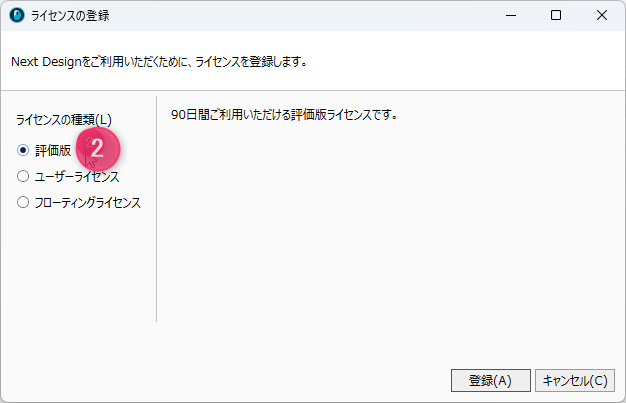
- When you launch Next Design for the first time, the license registration screen will appear.
- If you are using the evaluation version, select [Evaluation Version] from [License Type] on the left side and click the [Register] button.
Goal
Once license registration is complete, the Next Design start screen will be displayed.
The evaluation version allows you to use all features equivalent to the Enterprise Edition / Architect for 90 days after registration.
Install sample projects
Task Details
Sample projects for Next Design become available by installing additional packages.
In this hands-on guide, we will use the sample project included in the "Embedded Software Development Base Package" (Package name:EmbeddedSoftwareDevBase).
Procedure
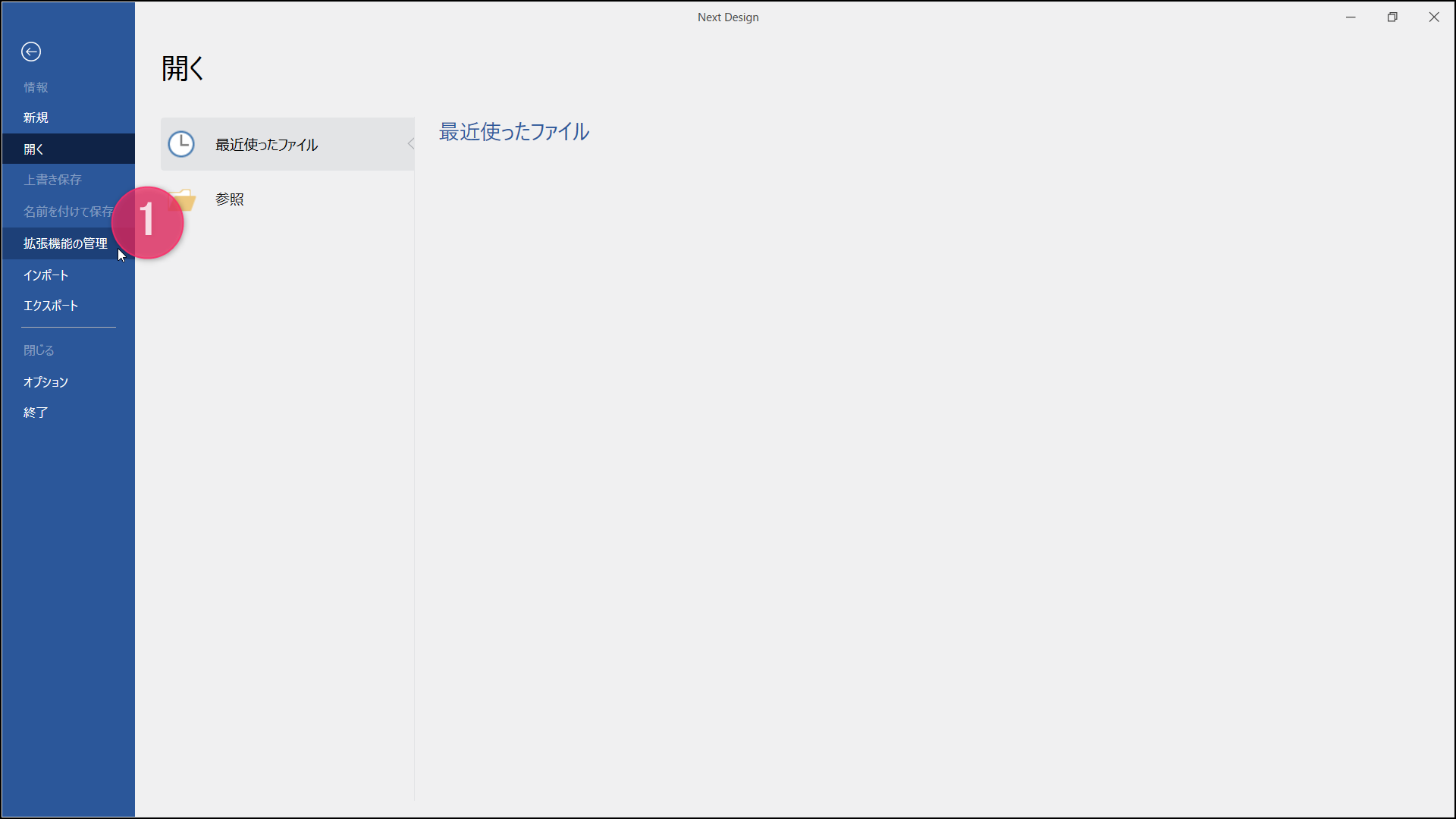
- Launch Next Design, select [File] > [Manage Extensions] from the ribbon to open the [Manage Extensions] dialog.
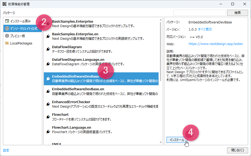
- In the [Manage Extensions] dialog, select [DENSO CREATE Official] from the list on the left to display the official packages in the center list.
- Select [EmbeddedSoftwareDevBase] from the list in the center to display the package details.
- Click the [Install] button to install the package.
- You also need to install the related package. You can proceed to the next step without restarting Next Design.
Goal
Follow the steps EmbeddedSoftwareDevBase to install the package.
Installing the related package
Task Details
To be able to view views such as state transition tables included in the sample, install the UML/SysML package (package name:UmlSysml).
If you have already installed the UML/SysML package, proceed to Step 4 and restart Next Design.
Procedure
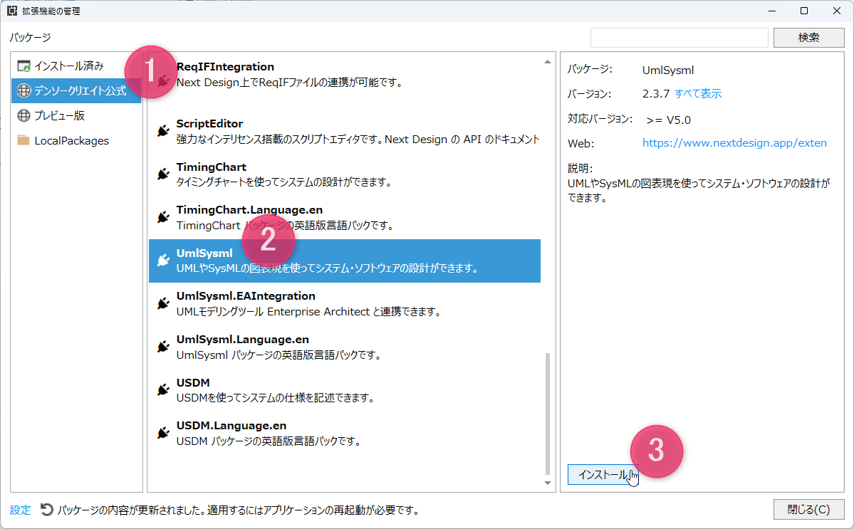
- In the [Manage Extensions] dialog, select [DENSO CREATE Official] from the list on the left and scroll down the center list.
- Select [UmlSysml] from the list in the center to display the package details.
- Click the [Install] button to install the package.
- Once the installation is complete, restart Next Design to enable the package.
- After restarting, verify that [Embedded Software Development] and [UML/SysML] are displayed under sample projects on the start screen.
- Clicking on [Embedded Software Development] within the sample projects will open the sample.
Goal
By following the steps to install the package and restarting Next Design, you will be able to open [Embedded Software Development] from the sample projects on the start screen.
2. Try it out
Take a look at the sample project
Task Details
Open the sample project [Embedded Software Development] (hereinafter referred to as the "sample") from the Next Design start screen to familiarize yourself with the Next Design screen layout and basic terminology while viewing the actual interface.
Procedure
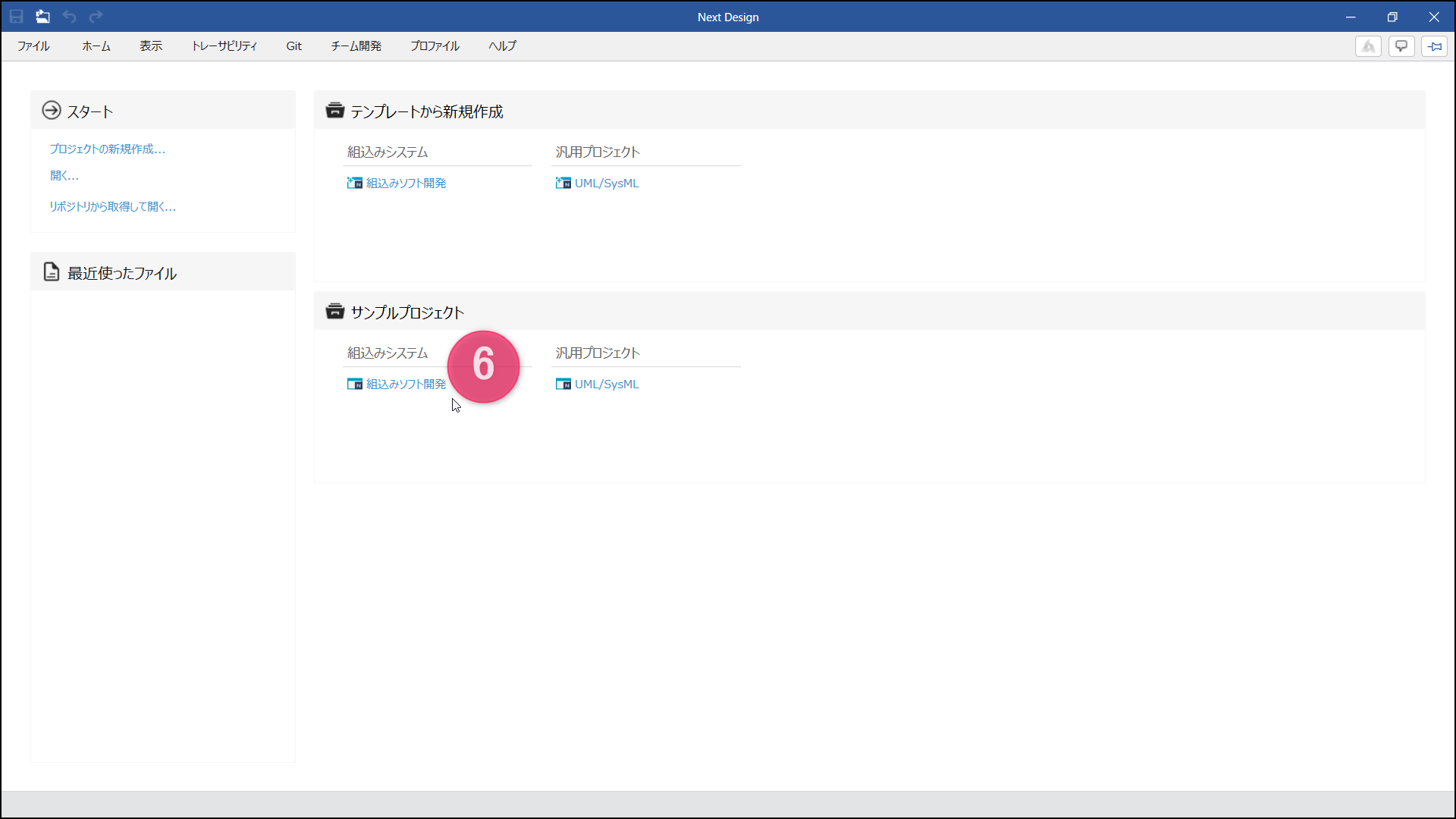
- When you launch Next Design, the [Start] screen appears, showing [Templates] for starting new projects and [Sample Projects] containing reference models.
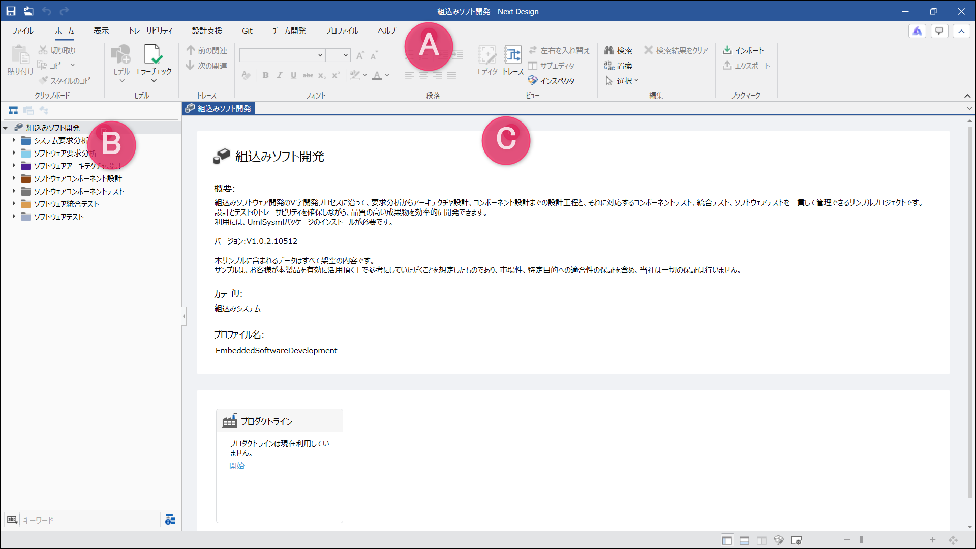
- Click [Embedded Software Development] from the sample projects to open the sample, and the screen will be displayed with the following layout.
- (A) Top of the screen: Ribbon-style menu
- (B) Left side: Tree-style [Model Navigator]
- (C) Center: [Main Editor] for editing models
The individual nodes displayed in a tree format within the [Model Navigator] on the left are called [Models]. These models have a hierarchical structure.
- Selecting the next model while expanding the tree in the [Model Navigator] displays the contents of the model—meaning the design information—in the [Main Editor].
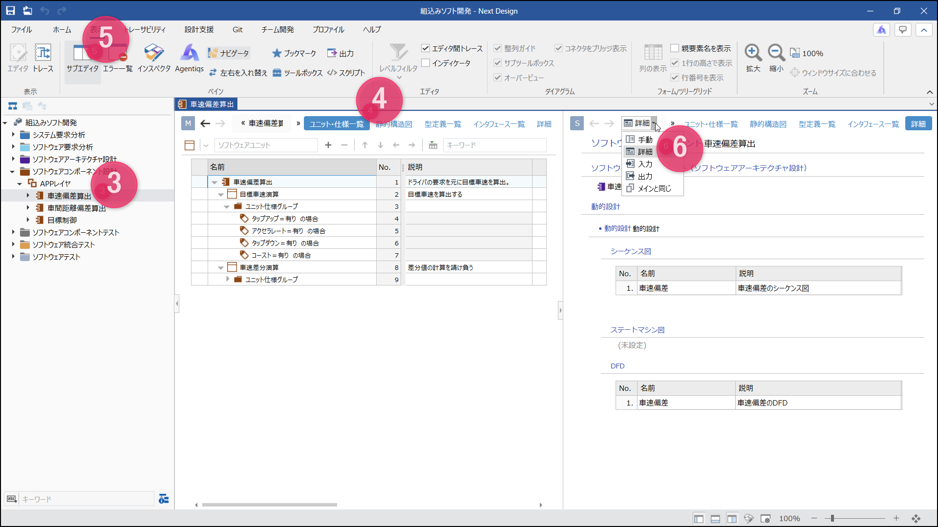
Embedded Software Development / Software Component Design / APP Layer / Inter-Vehicle Distance Offset Calculation
- On the upper right side of the [Main Editor], options for how the model is presented, such as [Unit/Specification List], [Static Structure Diagram], and [Type Definition List], are displayed. These are called [Views]. Selecting them allows you to switch the presentation format of the model.
- Toggling [View] > [Pane] > [Sub Editor] from the ribbon displays the [Sub Editor] next to the [Main Editor] on the right.
- In the [Sub Editor], you can select display modes such as [Manual], [Detailed], and [Input] from the upper dropdown list. Among these, the [Detailed] mode is the one used most frequently.
In detailed mode, the target model displayed in the [Sub Editor] automatically switches in synchronization with your selection operations on the main editor.
Goal
By using the samples, you can understand the basic screen layout and learn how to switch between models and views.
Experience Model Editing and View Reflection
Task Details
Experience editing a part of a model and seeing those changes automatically reflected in other views as well.
Procedure
- Following the same steps as before, select the next model to display the [Unit/Specification List] view.
Embedded Software Development / Software Component Design / APP Layer / Vehicle Speed Offset Calculation
- Verify that the model displayed in tree-grid format contains the following model.
Vehicle Speed Offset Calculation / Target Vehicle Speed Calculation
- Switching to the [Static Structure Diagram] view displays the model structure in an ER diagram format. Confirm that the [Target Vehicle Speed Calculation] model checked earlier is present on the left side of the diagram.
- Double-click the text string [Target Vehicle Speed Calculation] on the diagram, add [Processing] to the end, and change the model name to [Target Vehicle Speed Calculation Processing].
- Switching back to the [Unit/Specification List] view, verify that the change to the model name is reflected in this view as well.
Goal
Understand how the mechanism prevents design inconsistencies by separating the models that centrally manage design information from the views that switch the presentation formats of that design information.
3. Experience Design Scenarios
Understand the Design Workflow
Summary
Here, assuming a more concrete design workflow, you will experience the process of advancing software design using Next Design while switching between the views provided in the sample.
Expected Design Workflow
The samples are in a state where a complete design has already been performed. When starting a design from scratch, you need to follow the sample manual to proceed, but here we will pick up and experience the key points from a typical design workflow.
- Designing the Overall Architecture Structure
- Reviewing the Static Structure of the Architecture at a Glance
- Designing Individual Behaviors Using Optimal Design Methods
Detailed Description
- When designing the overall structure, you can use graphical views to design while grasping the overall structure.
- By switching views, you can view the design results in a tabular list. Looking at each column of the table makes it easier to notice omissions or input errors.
- You can design behaviors using predefined design methods, such as sequence diagrams, state machine diagrams, and state transition tables.
Goal
By using appropriate views according to the design workflow, you can prevent omissions while maintaining the consistency of design information and unifying expression methods.
Designing the Overall Architecture Structure
Task Details
In the early stages of design, you can use an ER diagram format view, which allows graphical representation, to design the overall architecture structure and get a bird's-eye view of the entire design target.
By using the ER diagram format view, you can experience grasping the static structure of the target model and the relationships between constituent elements graphically.
Procedure
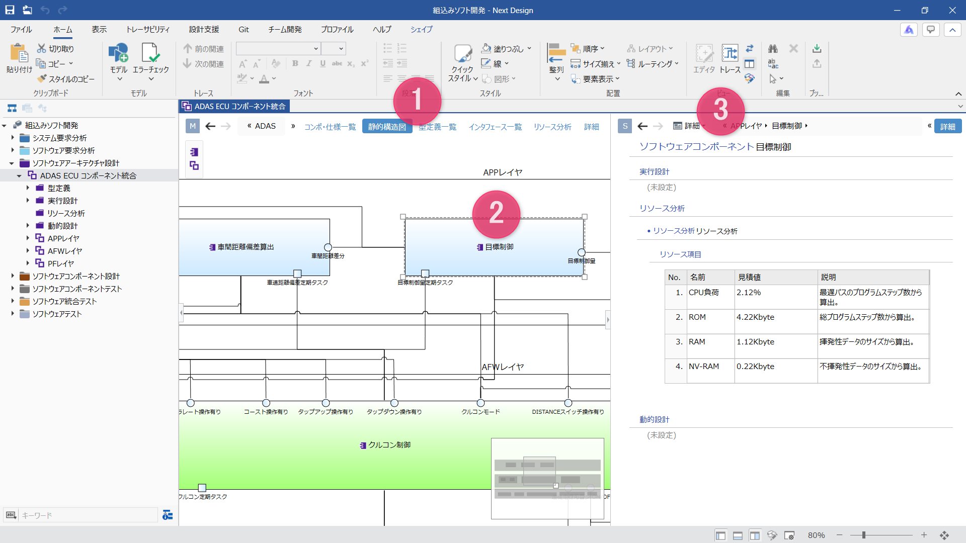
- Similar to the previous procedure, with the following model open, displaying the [Static Structure Diagram] view will show the overall architecture structure by layers and components as a diagram.
Embedded Software / Software Architecture Design / ADAS ECU Component Integration
💡 Hint:
If the diagram is large and requires scrolling, you can pan the screen in all directions by dragging while holding down the right mouse button on the diagram. - On the ER diagram, layers and components are represented as diagrams with a nested structure, and connected related models allow you to intuitively grasp the structure and relationships of the design target. For example, within the [APP Layer] frame, there are blocks representing three components: [Vehicle Speed Deviation Calculation], [Inter-vehicle Distance Deviation Calculation], and [Target Control], showing that they have relationships with other components.
- By using the sub-editor's [Details] mode in combination with that state, you can simultaneously check the details of the component selected on the ER diagram in the sub-editor while getting a bird's-eye view of the entire image on the ER diagram.
Goal
You can understand that by using the ER diagram and sub-editor in combination in the early stages of design, you can proceed with structural design while getting a bird's-eye view of the design target.
Reviewing the Static Structure of the Architecture at a Glance
Task Details
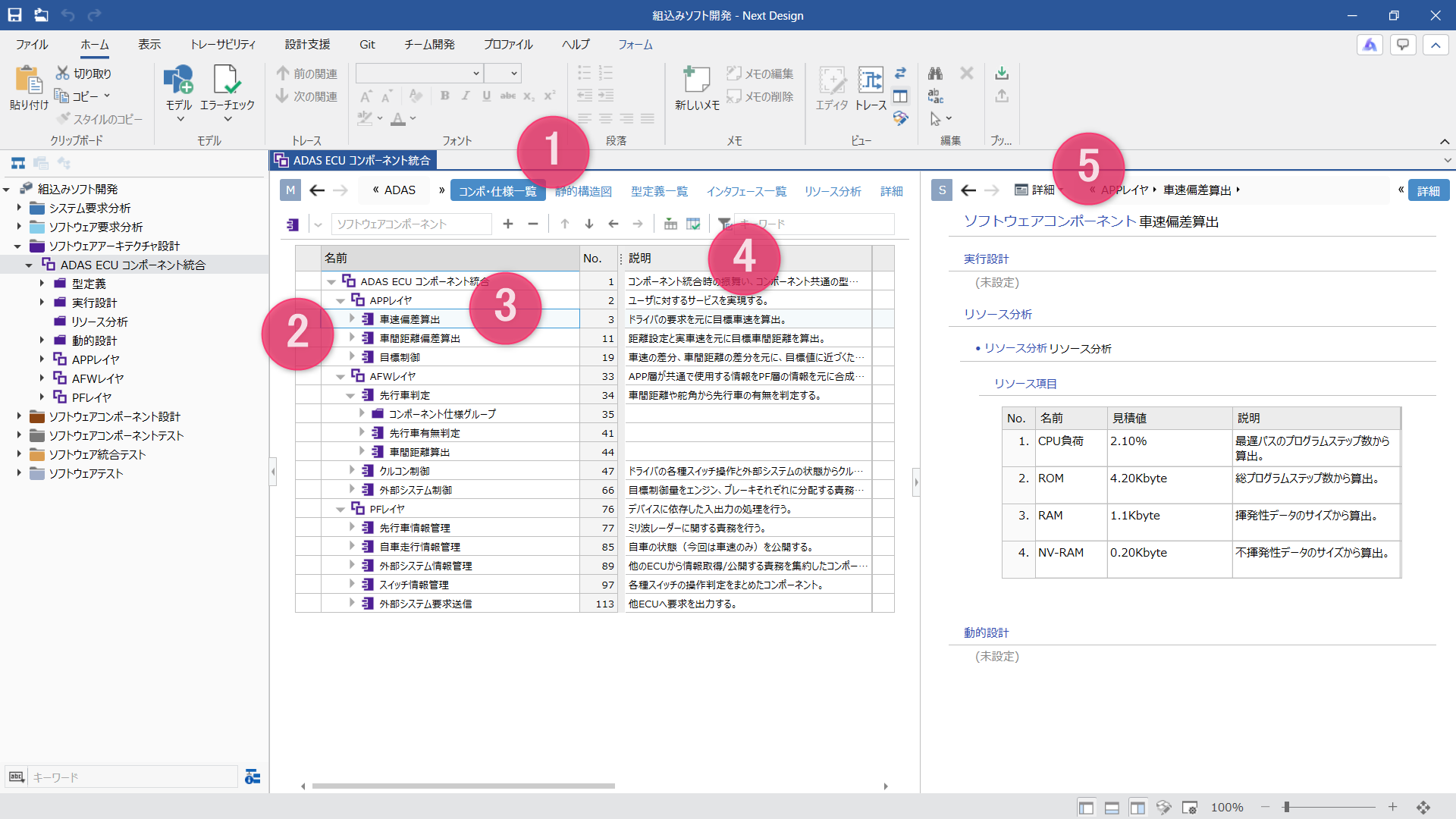
While designing the overall structure in an ER diagram format view, you can switch to a tree-grid format view to review the hierarchized static structure of the architecture at a glance.
By using the tree-grid format view, you can experience that the hierarchical model structure is displayed in a tabular format while maintaining its hierarchy, making it easier to notice omissions or input errors in design information because names and items can be viewed together.
Procedure
- Similar to the previous procedure, select the following model and switch to the [Component & Specification List] view to display the components under the layer in a tree-grid format.
Embedded Software / Software Architecture Design / ADAS ECU Component Integration
- Confirming that the components under the layer are lined up in a tree format shows that you can review them in a list while maintaining parent-child relationships.
- When tracing elements in the following hierarchy, you can confirm that the structure seen in the diagram is also represented as the same model in the list.
ADAS ECU Component Integration / APP Layer / Vehicle Speed Deviation Calculation
- While tracing parent-child relationships in the list, you can edit or check their values in the [Description] column.
- By selecting a row from the [Main Editor] list and using the [Details] mode in the sub-editor simultaneously, you can edit or check the details of individual elements in any desired view.
Goal
Viewing items in a tree-grid format allows you to get an overview of the design structure and individual items at a glance, demonstrating how you can design while switching between different views according to your purpose.
No matter which view you use for designing, your design information always remains consistent. This is because the design information is centrally managed as model data.
Designing Individual Behaviors Using Optimal Design Methods
Task Details
The sample supports the following design methods for designing dynamic software behavior:
- Sequence Diagram
- DFD
- State machine diagram / State transition table
- Flowchart
Experience how appropriate design methods are readily available for each design target, allowing you to design without hesitation regarding how to represent it.
Procedure
- Select the next model in the model navigator to display the [Details] view.
Embedded Software Development / Software Component Design / APP Layer / Vehicle Speed Offset Calculation
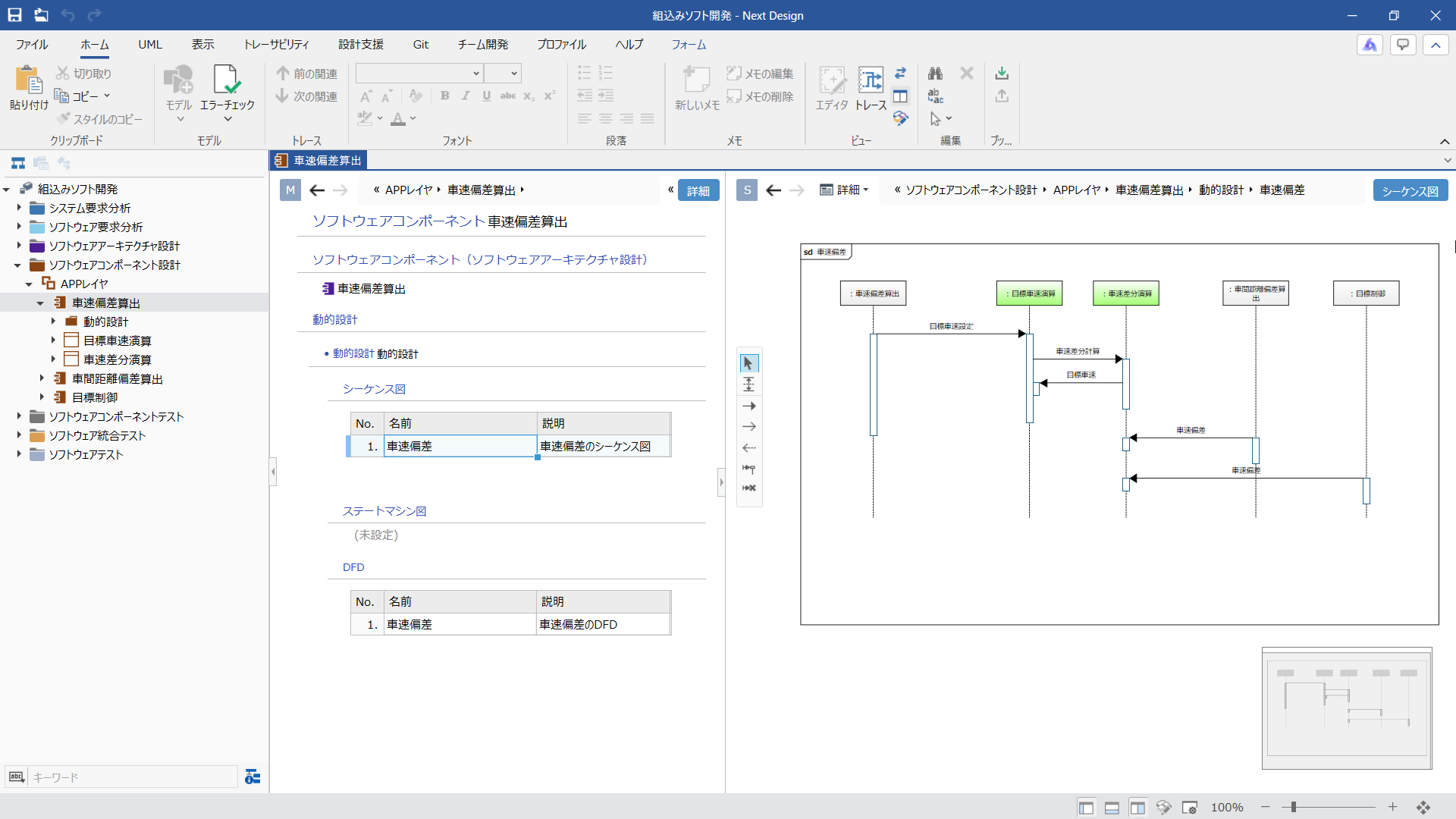
- With the sub-editor set to [Details] mode, select the [Vehicle Speed Deviation] row under [Sequence Diagram] in [Dynamic Design] on the main editor to display and edit the [Sequence Diagram] view in the sub-editor.
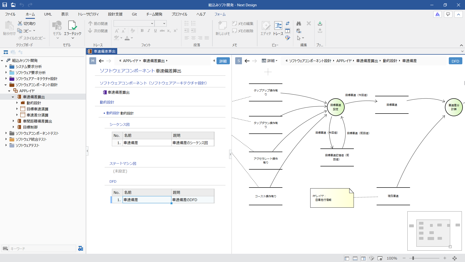
- Similarly, in the [Details] view of the main editor, select the [Vehicle Speed Deviation] row under [DFD] in [Dynamic Design] to display and edit the [DFD] view in the sub-editor.
Procedure
- Select the next model in the model navigator to display the [Details] view.
Embedded Software Development / Software Component Design / APP Layer / Inter-Vehicle Distance Offset Calculation
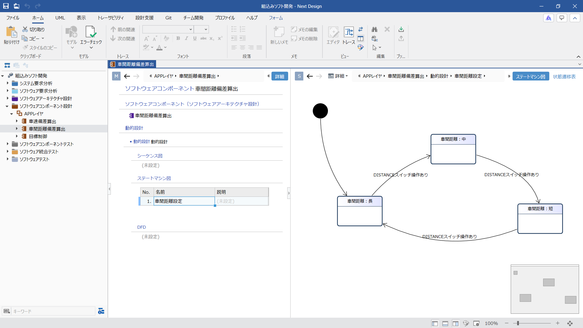
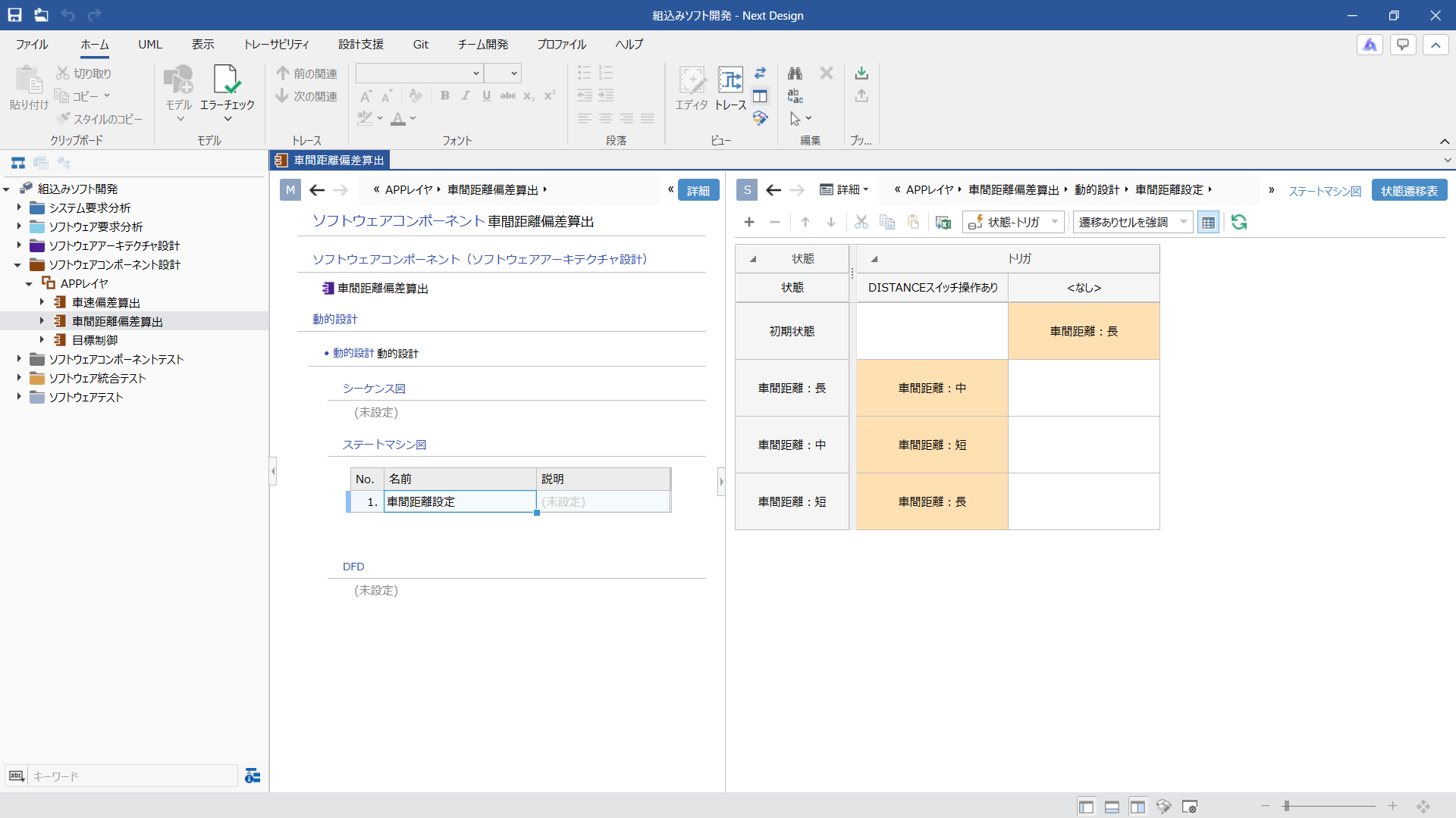
- In the [Details] view of the main editor, select the [Inter-Vehicle Distance Setting] row under [State Machine Diagram] in [Dynamic Design] to display and edit the [State Machine Diagram] view in the sub-editor.
You can also switch from the [State Machine Diagram] view to the [State Transition Table] to edit.
Procedure
- Select the next model in the model navigator to display the [Details] view.
Embedded Software Development / Software Component Design / APP Layer / Vehicle Speed Deviation Calculation / Target Vehicle Speed Calculation / Target Vehicle Speed Setting
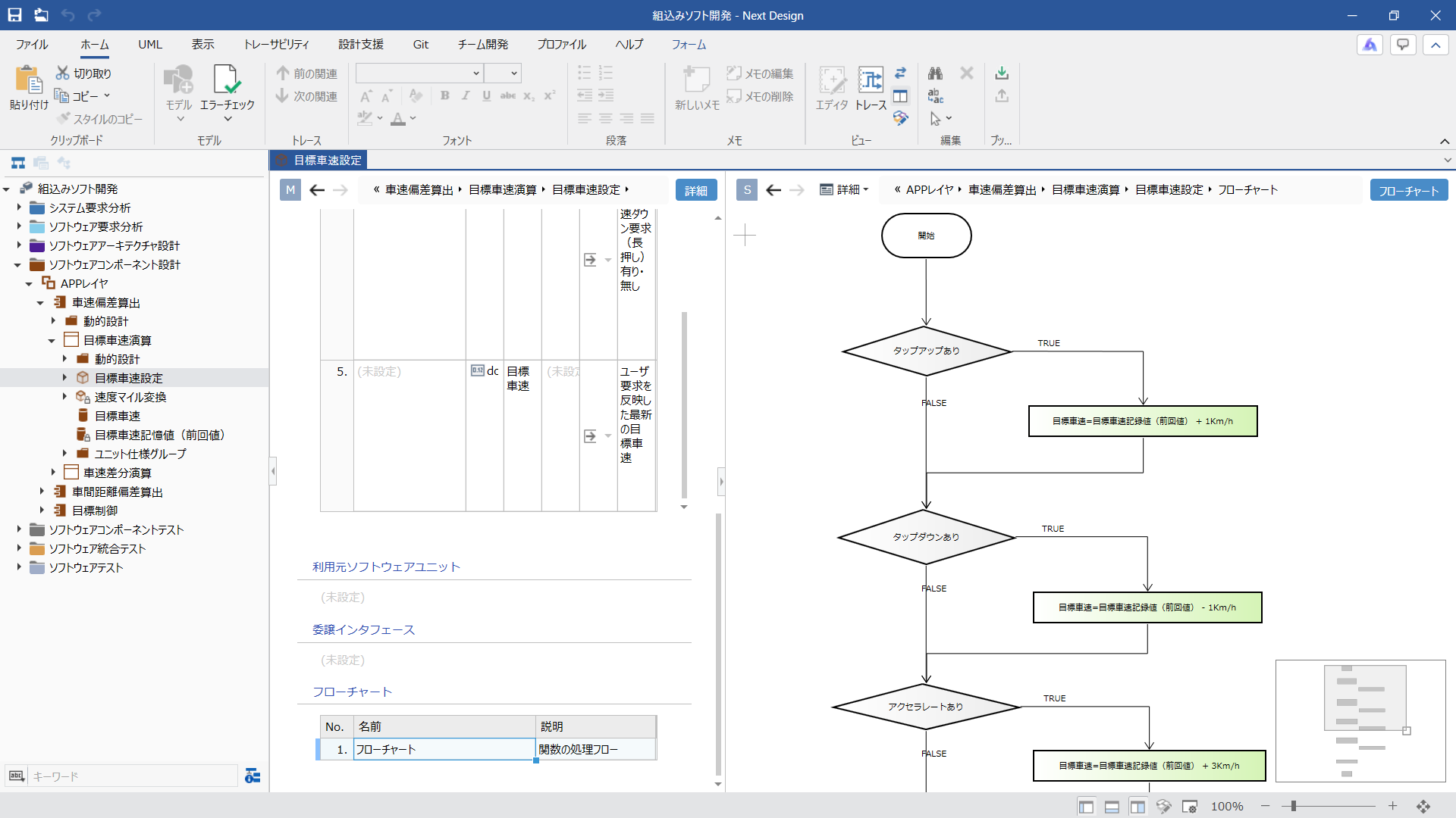
- Scrolling to the bottom of the main editor's [Details] view displays the [Flowchart] item. Selecting the [Flowchart] row displays and enables editing of the [Flowchart] view in the sub-editor.
Goal
Understand how you can select the optimal design method for your design target and use dedicated views tailored to it to design individual behaviors. Even when designing behaviors, you can proceed with your design using views suited for embedded software development while maintaining single-source model management.
4. Experience Traceability
Designing with Requirements as Input
Open in a new window
Open in a new window
Task Details
One of Next Design's unique features is the ability to derive models from upstream processes. This allows you to naturally ensure traceability by designing with requirements as input, eliminating the hassle of having to re-establish traceability after design completion.
Here, you will experience how trace information is automatically recorded by dragging and dropping between the main editor and sub-editor, allowing you to proceed with design while deriving design models related to requirements models.
Procedure
- Select the next requirements model in the model navigator to display the [Requirements List] view in the main editor.
Embedded Software / Software Requirements Analysis / Advanced Driving System Software / ADAS ECU Control Software
- Switch the sub-editor display mode to [Manual] so that the specified model is always displayed in the sub-editor.
- Drag the next design target model from the model navigator. Drop that model onto the upper part of the sub-editor to display it in the sub-editor. Verify that the [Component / Specification List] view is displayed.
Embedded Software / Software Architecture Design / ADAS ECU Component Integration
⚠️ Note:
At this time, start dragging while holding down the mouse button on the model navigator. If you release the mouse button, that model will be selected and displayed in the main editor. - Right-click any model in the main editor and click [Tree] > [Expand All] from the context menu to display all elements of the requirements model.
Similarly, expand all items in the sub-editor tree to display all elements of the design target model.
This results in a state where the requirements model is displayed in the main editor and the design target model in the sub-editor, preparing you to design the target model using the requirements model as input.
- The sample is already designed, and trace lines representing trace information are displayed between the elements of the requirements model on the left and the design target model on the right. This inter-editor trace feature allows you to verify the relationship between requirements and design while designing.
- Derive a design model from a requirements model as follows.
Requirements Model: 16th row of the main editor [While cruising with ACC at a constant speed...]
Design Model Addition Destination: 5th row of the sub-editor [Functional Specification]Pointing to the rightmost column of the above requirements model in the main editor displays a gray [+] icon. Drag that [+] icon and drop it onto the above design model addition destination in the sub-editor. With this single operation, a new element is added to the design model and linked to the requirements model with a trace line.
- To link trace lines between existing requirements model elements and design model elements, drag the requirements model [+] icon and drop it onto the orange [○] icon displayed in the leftmost column of the existing design model. This also allows you to manually add trace information later.
Goal
By using "Model Derivation," a unique feature of Next Design, to derive design models from requirements models, trace information is automatically recorded during the design process, allowing you to understand how to eliminate redundant work while ensuring comprehensive traceability.
Checking Traceability Across Processes
Open in a separate window
Open in a separate window
Task Details
Next Design includes a dedicated screen for checking traceability.
The trace view allows you to list traceability across processes by displaying models linked by trace information across multiple lanes.
Here, you will experience using the trace view to check traceability from requirements to design and from design to test, find omissions, or jump to models whose details you want to check.
Procedure
- Click [Traceability] > [View] > [Trace] on the ribbon to display the trace view.
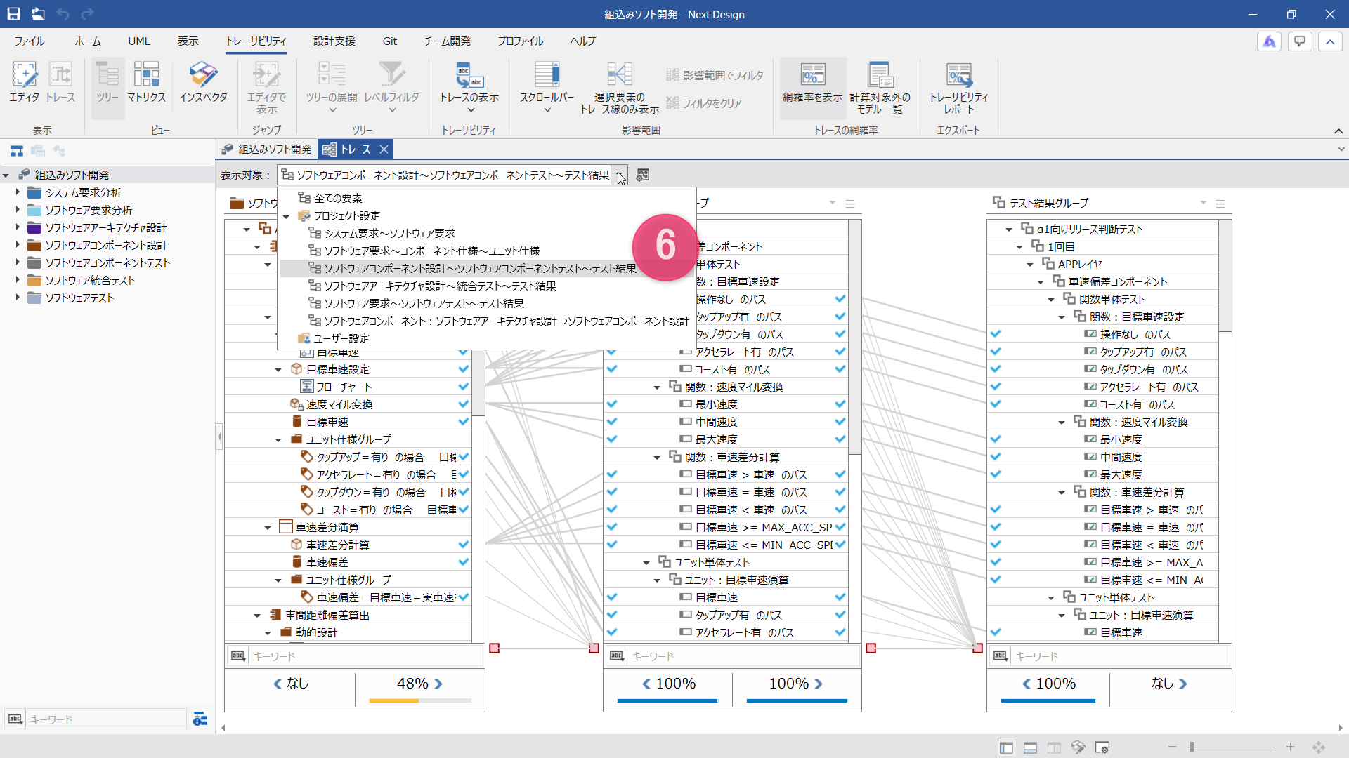
- Select the next option from [Display Target] at the top of the trace view to switch the target.
Software Requirements ~ Component Specification ~ Unit Specification
Based on the predefined options set for your purpose, models corresponding to requirements, design, and detailed design are arranged across multiple lanes, allowing you to check dependency relationships across development phases.
- Right-click any model in each lane and select [Tree] > [Expand All] from the context menu to display all elements. This displays trace information set between models across phases in a graph, allowing you to trace dependencies across phases.
- Clicking any model on a lane highlights the models associated through trace information across all phases, which is useful for analyzing the impact range during requirement or design changes.
- Check for missing trace information using the coverage rate displayed at the bottom of each lane and the icons shown on the left and right of each element. The coverage rate gives you an overview of the alignment status between phases, while the [!] icon helps you quickly identify models without trace information, making it easy to spot potential omissions.
- Similarly, you can switch the view using the options in [Display Target] to check the adequacy of tests against the design.
Software Component Design ~ Software Component Test ~ Test Results
These options can be freely added or modified according to your development process and traceability verification viewpoints.
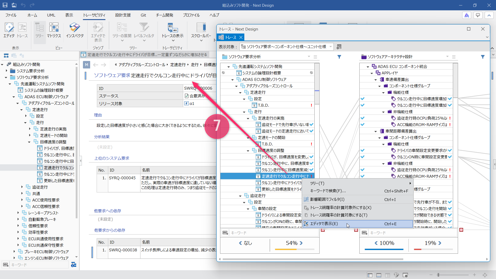
- If you want to check details for a specific model, right-click it and select [Show in Editor] from the context menu. The corresponding model is displayed in the editor, allowing you to seamlessly dive deeper into the omissions noticed in the trace view or the design information of the model.
Note that the trace page and models are displayed in separate tabs. Dragging the trace page tab up or down detaches it into a separate window, allowing you to view the trace page and models simultaneously.
Goal
By utilizing trace information between models and the trace view that lists them, you can understand the continuous cycle of checking traceability across phases and reviewing individual model details as needed.
Let's move on
In the next part, you will experience how Next Design can be useful for your own work.